
PIC User Manual
Introduction
This manual covers the use of Microchip™ PIC microcontrollers within iCircuit, including the use of firmware from hexadecimal files or assembler source code. For more details on a microcontroller, consult the manual for the specific PICmicro product you are using. This document is part of iCircuit property of Krueger Systems.
Supported processors
Currently, iCircuit supports most baseline and some mid-range processors, however, support for more processors is contemplated in the future. This includes the following processors:
| p10f200 | p10f202 | p10f204 | p10f206 | p10f220 | p10f222 |
|---|---|---|---|---|---|
| p12f508 | p12f509 | p12f510 | p16f54 | p16f57 | p16f59 |
| p16f505 | p12f506 | p10f320 | p10f322 | p16f877a |
PICmicro
Including PICmicro microcontrollers in your simulations is now as easy as adding the element and entering a machine code source.
Adding PICs
To add a PIC to your simulation, click the + button on the toolbar and select the Digital category.

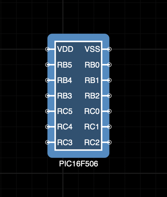
Look for the model in the list of available PICs

Machine Code (Firmware)
Adding machine code for execution is equally simple, you need a hexadecimal file or assembler source code.
Hexadecimal Files
Hex files are the result of compiling source code (in any programming language) with a specialized compiler for microcontrollers such as XC8 or JAL, or they can even be the result of assembling code with assemblers such as MPASM or GPASM.
To make use of these files it is necessary to have a circuit ready to handle the code to be simulated, as shown in the following image
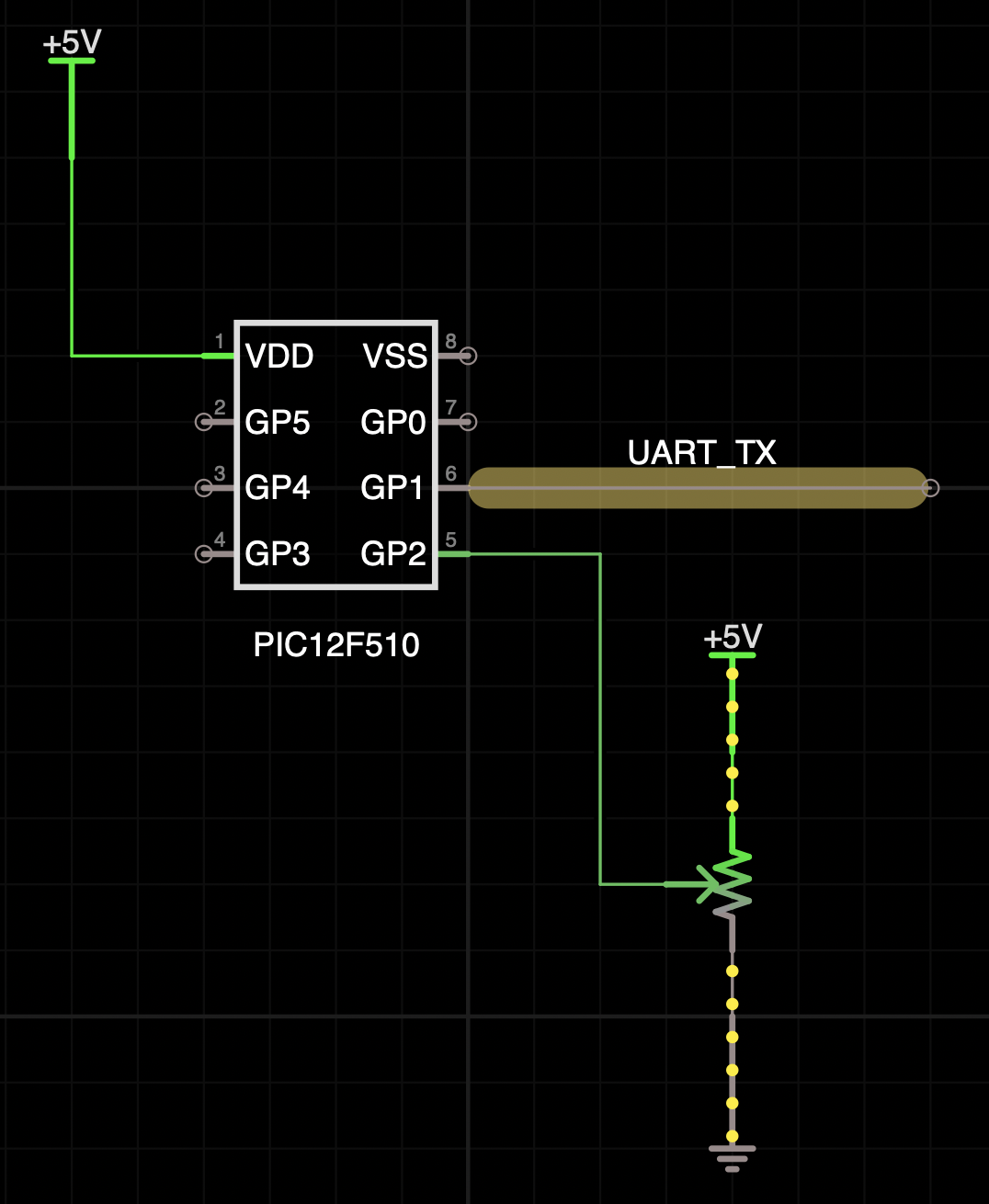
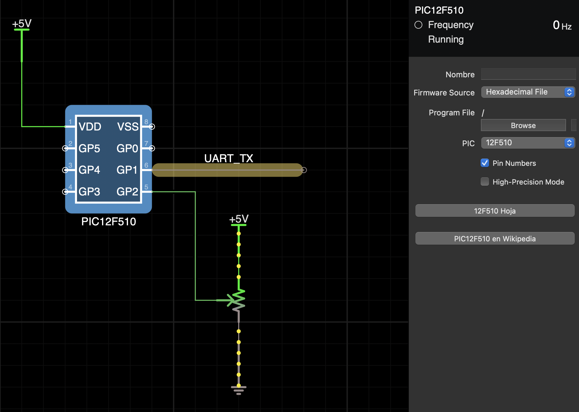
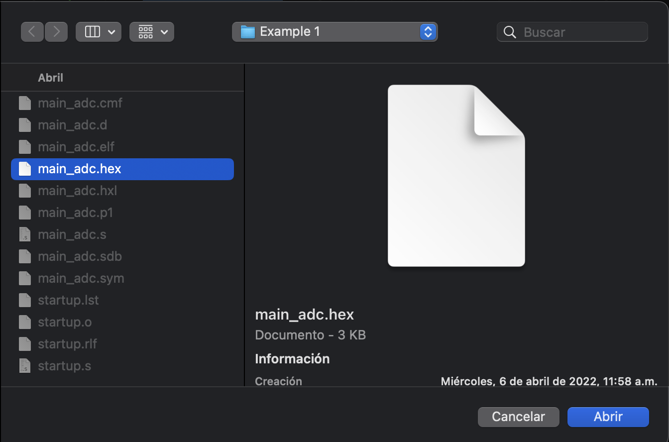
The machine code source will default be hexadecimal files, so you just need to press the Browse button and locate the firmware.

This firmware is in charge of reading a channel of the ADC and encoding the information to send it through soft UART. The code used is presented below and was compiled with the help of Microchip™ XC8 (for more details about XC8 and how to compile the code, consult the user’s guide).
#include <xc.h>
// *** Microcontroller MIPs (FCY) *** //
#define FOSC_ 8000000       // * target device system clock frequency: Max Frequency is 8MHz for 12F510 * //
#define _XTAL_FREQ FOSC_    // * required for __delay_ms, __delay_us macros * //
// CONFIG bits that are part-specific for the PIC 12F510
#pragma config  OSC   = IntRC   //Oscillator Selection bits (internal RC oscillator)
#pragma config  WDT   = OFF     //Watchdog Timer Enable bit (WDT disabled)
#pragma config  CP    = OFF     //Code protection bit (CP is ON)
#pragma config  MCLRE = OFF     //GP3/MCLRE Pin Function Select bit (GP3/MCLRE pin function is GP3)
#pragma config  IOSCFS= ON     //OFF =  4 MHz INTOSC speed; ON = 8 MHz INTOSC speed
// *************************** I/O Pin Definition *************************** //
//---------- Input and Output Pin(s) ----------
#define UART_TX     GPIObits.GP1    //Pin 6
#define LED             GPIObits.GP4    //Pin 3
// *************************** Definitions ********************************** //
#define OneBitDelay     11  // 10 for 12F510 @ 8MHz, TMR0 prescaler 1:16, Baudrate 9600
#define DataBitCount    8   // no parity, no flow control
#define FALSE 0
#define TRUE 1
#define OFF 0
#define ON 1
// ***************************** Variables ********************************** //
unsigned char i, POT_value;
unsigned char TempData, Digit_100 = 0, Digit_10 = 0, Digit_1 = 0;
// ******************************** SETUP *********************************** //
void SETUP_initialize(void) {
    OSCCAL = 0b11111110;    // Max frequency is set; b-7:1 for calibration bit-0 should be written as 0
    TRISGPIO = 0b00001100;  // '1': for inputs; '0': for outputs
    CM1CON0 = 0b11110110;   // Analog Comparator set OFF
    ADCON0 = 0b01111001;    // AN2 (GP2) is selected as Analog Channel
    OPTION = 0b11000011;    // Bit7:RBWU disabled (1), Bit6:RBPU disabled (1),
}
// *************************** UART Initialize ****************************** //
void InitSoftUART(void){
    UART_TX = 1;
}
// ***************************** UART Transmit ****************************** //
void UART_Transmit(unsigned char SendValue) {
    unsigned char j;
    UART_TX = 0;
    TMR0 = 0;
    while (TMR0 < OneBitDelay);
    for (j=0;j<DataBitCount;j++) {
        TempData = SendValue & 1;
        if (TempData)
            UART_TX = 1;
        else
            UART_TX = 0;
        SendValue >>= 1;
        SendValue &= 0b01111111;
        TMR0 = 0;
        while (TMR0 < OneBitDelay);
    }
    UART_TX = 1;
    TMR0 = 0;
    while (TMR0 < OneBitDelay);
}
// **************************** Decimal to BCD ****************************** //
unsigned char GetDigit(unsigned char n, unsigned char k) {
    while (n--)
        k /= 10;
    return k%10;
}

void main(void) {
    SETUP_initialize();     // Initialize SETUP
    InitSoftUART();
    ADCON0bits.GO = TRUE;   //Start ADC to read POT value
    POT_value = 0;          //Initial value of POT_value is 0
    LED = OFF;              //Initial state of LED is OFF
    __delay_ms(10);         //delay for AD conversion (couple of ms is enough)
    for(;;) {
        if (!ADCON0bits.GO) {    //if GO bit is clear, ADC is done and ready to read
            POT_value = ADRES;    //ADRES is the register ADC value stored in
            ADCON0bits.GO = TRUE; //Restart ADC
        }
        Digit_100 = GetDigit(2,POT_value);
        Digit_10 = GetDigit(1,POT_value);
        Digit_1 = GetDigit(0,POT_value);
        UART_Transmit ('<');
        __delay_ms(15);
        UART_Transmit (Digit_100 + 48);
        __delay_ms(15);
        UART_Transmit (Digit_10 + 48);
        __delay_ms(15);
        UART_Transmit (Digit_1 + 48);
        __delay_ms(15);
        UART_Transmit ('>');
        __delay_ms(250);
    }
}
Assembly Code
Assembly language is a low-level programming language, composed of mnemonics that represent the basic instructions of the computer or microcontroller in this case.
To make use of this programming language to compile firmware, an assembler was developed (for more details visit the Circuit ASM section). As with the hexadecimal files, you must have a circuit where you want to perform the simulation as follows.

Next, access the PIC parameters by selecting it from the circuit elements.

Now it is required to change the firmware source to assembly code using the selector

Once the firmware source is changed, the code editor will be enabled, which will provide help to detect syntax errors, at this point, you must enter the code you want to run

Once a valid code has been entered, the corresponding machine code will be generated, and it is planned to be able to generate hexadecimal files in the future.
The specific example shown above is used to generate a blink on an LED of approximately 0.5 seconds, taken from an example bank and adapted to Circuit ASM. The complete code is presented below.
list p=16f506
#include "p16f506.inc"

; CONFIG
; __config 0xFFBC  ; run at 4 Mhz
 __CONFIG _OSC_IntRC_RB4EN & _WDT_OFF & _CP_OFF & _MCLRE_ON & _IOSCFS_OFF

; PLACE VARIABLE DEFINITIONS GO HERE
CBLOCK
sREG        ; shadow copy of register
dc1     ; delay loop counter
dc2     ; delay loop counter
ENDC

;*******************************************************************************
; Reset Vector
;*******************************************************************************

    org    0x0000           ; processor reset vector
    MOVWF   OSCCAL
RES_VECT
    GOTO    START           ; go to the beginning of the program

;***** Initialisation
START
    movlw   b'110111'           ; configure C3 as output
    tris    PORTC           ; store contents of W to trisc register
    clrf    sREG            ; start with shadow register zeroed

;**** Main Loop
MAIN_LOOP
    ; toggle LED on C3
    movf    sREG, w         ; get shadow copy of C3, move W to sREG
    xorlw   b'001000'           ; toggle bit at C3
    movwf   sREG            ;  in shadow register
    movwf   PORTC           ; write to PORTC

    ; delay 500 ms
    movlw   .244            ; outer loop: 244 x (1023 + 1023 + 3) + 2
    movwf   dc2             ;   = 499, 958 cycles
    clrf    dc1             ; inner loop: 256 * 4 - 1
dly1                    ; inner loop 1 = 1023 cycles
    NOP                 ; do nothing
    decfsz  dc1, f          ; check register if zero, skip goto else dec
    goto    dly1            ; loop
dly2
    NOP                 ; do nothing
    decfsz  dc1, f          ; check register if zero, skip goto else dec
    goto    dly2

    decfsz  dc2, f
    goto    dly1

    GOTO MAIN_LOOP          ; loop forever

    END
Notes
- By default, the PICs will try to run with a relatively low bandwidth
(11kHz), if higher bandwidth is required or sounds need to be
reproduced, a bandwidth of 44.1kHz should be used, this is achieved by
accessing the global properties, selecting the canvas or the circuit
grid.

- The architecture (baseline or mid-range) when you’re using assembly code will be determined based on the PIC being used.
Circuit ASM
As part of the efforts to simplify and make easier the use of PICs within iCircuit, we designed our assembler, with some limitations, but certainly capable of issuing machine code without any problem.
Tool Flow
Circuit ASM can only be used in absolute Asm mode, which means that an assembly language source file is directly converted into a hex file (machine code). This method is absolute because the final addresses are hard coded into the source file.
Absolute mode is simple to understand and use. It only requires one tool. Most of the examples on Microchip’s website use absolute mode.
Relocatable mode is not yet supported at this time but is planned for the near future.
Running Circuit ASM
Running Circuit ASM is as simple as selecting assembly code as the firmware source (see Assembly Code section) and start writing your code.
The supported instruction sets are: * PIC Baseline * PIC Mid-Range
Syntax
Circuit ASM syntax is based on gpasm, so in general, many syntax rules were respected (for more information about gpasm see gpasm guide), however, not everything was implemented in this assembler.
File Structure
The Circuit ASM source files consist of a series of lines that can contain a label (starting in column 1) or an operation (starting in any column after 1), both, or neither. Comments follow a “;” character, and are treated as a newline. Labels may be any series of the letters A-z, digits 0-9, and the underscore (“_”); they may not begin with a digit. Labels may be followed by a colon (“:”).
An operation is a single identifier (the same rules as for a label above) followed by a space, and a comma-separated list of parameters. For example, the following are all legal source lines:
                      ; Blank line
loop sleep            ; Label and operation
     incf     6, 1    ; Operation with 2 parameters
     goto     loop    ; Operation with 1 parameter
Numbers
Circuit ASM supports many ways to specify a number. It fully supports the numerical syntax of gpasm. The following table summarizes the alternatives.
| Base | General Syntax | 15 decimal written as |
|---|---|---|
| Binary | B’[01]*’ | B’1111’ |
| Octal | O’[0-7]*’ | O’17’ |
| Decimal | D’[0-9]*’ | D’15’ |
| Hex | H’[0-F]*’ | H’F’ |
| Hex | 0x[0-F]* | 0xF |
When you write a number without a specifying prefix such as “45”, Circuit ASM uses the current radix (base) to interpret the number. You can change this radix with the “p” option of the LIST directive, RADIX directive is not yet implemented. The default radix is hexadecimal. If you do not start hexadecimal numbers with a digit, Circuit ASM will attempt to interpret what you’ve written as an identifier. For example, instead of writing F1, write either 0F1, 0xF1, or H’F1’
Case is not significant when interpreting numbers.
Several legacy mpasm number formats are also supported. The table below summarizes them
| Base | General Syntax | 15 decimal written as |
|---|---|---|
| Binary | [01]*b | 1111b |
| Octal | q’[0-7]*’ | q’17’ |
| Octal | [0-7]*o | 17o |
| Octal | [0-7]*q | 17q |
| Decimal | [0-9]*d | 15d |
| Hex | .[0-9]* | .15 |
| Hex | [0-F]*h | Fh |
You can write the ASCII code for a character X using ‘X’.
Preprocessor
The only preprocessing instruction supported so far is “include”. These instructions will make the ASM Circuit fetch source lines from the file specified until the end of the file, and then return to the original source file at the line following the include.
The rest of the instructions such as define, undefine and v will be added in future updates.
Processor Header Files
Circuit ASM can access the Microchip processor header files. These files contain processor-specific data that is helpful in developing PIC applications. Use the INCLUDE directive to use the appropriate file in your source code. Only the name of the file is required.
Local Header Files
Circuit ASM also supports the use of local files, through an element called “Heade File”, in which you can load pre-existing files or create them from scratch, edit and rename them.
Predefined Constants
The only predefined constant is the device ID, which can be found in
the case of the PIC 12F510 as __12F510.
Directives
Circuit ASM supports most of the gpasm directives, clearly excluding all those used in relocatable mode.
Code Generation
To set the PIC memory location where Circuit ASM will start assembling code use ORG. If you don’t specify an address with ORG, Circuit ASM assumes 0x0000.
Configuration
You can choose the fuse settings, also known as Configuration Bits, for your PIC implementation using the __CONFIG directive. Naturally you should make sure that these settings match your PIC hardware design.
For now only mpasm compatibility mode is supported, however, support for CONFIG and __FUSES directives will be added in the future.
The __MAXRAM and __BADRAM directives specify which RAM locations are legal. These directives are mostly used in processor-specific configuration files.
Dollar Sign ($)
The dollar symbol expands the address of the instruction currently being assembled. The value given by this expression can be manipulated like any other number and can be used as a shortcut for writing loops without labels.
Directive Summary
A large part of the directives supported by gpasm are supported by Circuit ASM, for more information about each directive and its syntax please visit the gpasm user manual.
The following is a list of supported directives:
- __BADRAM
- __CONFIG
- __MAXRAM
- CBLOCK
- END
- ENDC
- EQU
- IFDEF
- IFNDEF
- LIST
- MESSG
- ORG
- PAGESEL
Instructions
Baseline Instruction Set Summary
| Mnemonic | Operands | Description | Cycles | 12-bit Opcode MSb……LSb |
Status Affected | Notes |
|---|---|---|---|---|---|---|
| ADDWF | f,d | Add W and f | 1 | 0001 11df ffff | C,DC,Z | 1,2,4 |
| ANDWF | f,d | AND W with f | 1 | 0001 01df ffff | Z | 2,4 |
| CLRF | f | Clear f | 1 | 0000 011f ffff | Z | 4 |
| CLRW | Clear W | 1 | 0000 0100 0000 | Z | ||
| COMF | f,d | Complement f | 1 | 0010 01df ffff | Z | |
| DECF | f,d | Decrement f | 1 | 0000 11df ffff | Z | 2,4 |
| DECFSZ | f,d | Decrement f, Skip if 0 | 1(2) | 0010 11df ffff | None | 2,4 |
| INCF | f,d | Increment f | 1 | 0010 10df ffff | Z | 2,4 |
| INCFSZ | f,d | Increment f, Skip if 0 | 1(2) | 0011 11df ffff | None | 2,4 |
| IORWF | f,d | Inclusive OR W with f | 1 | 0001 00df ffff | Z | 2,4 |
| MOVF | f,d | Move f | 1 | 0010 00df ffff | Z | 2,4 |
| MOVWF | f | Move W to f | 1 | 0000 001f ffff | None | 1,4 |
| NOP | No Operation | 1 | 0000 0000 0000 | None | ||
| RLF | f,d | Rotate left f through Carry | 1 | 0011 01df ffff | C | 2,4 |
| RRF | f,d | Rotate right f through Carry | 1 | 0011 00df ffff | C | 2,4 |
| SUBWF | f,d | Subtract W from f | 1 | 0000 10df ffff | C,DC,Z | 1,2,4 |
| SWAPF | f,d | Swap f | 1 | 0011 10df ffff | None | 2,4 |
| XORWF | f,d | Exclusive OR W with f | 1 | 0001 10df ffff | Z | 2,4 |
| BCF | f,b | Bit Clear f | 1 | 0100 bbbf ffff | None | 2,4 |
| BSF | f,b | Bit Set f | 1 | 0101 bbbf ffff | None | 2,4 |
| BTFSC | f,b | Bit Test f, Skip if Clear | 1(2) | 0110 bbbf ffff | None | |
| BTFSS | f,b | Bit Test f, Skip if Set | 1(2) | 0111 bbbf ffff | None | |
| ANDLW | k | AND literal with W | 1 | 1110 kkkk kkkk | Z | |
| CALL | k | Subroutine Call | 2 | 1001 kkkk kkkk | None | 1 |
| CLRWDT | Clear Watchdog Timer | 1 | 0000 0000 0100 | TO,PD | ||
| GOTO | k | Unconditional Branch | 2 | 101k kkkk kkkk | None | |
| IORLW | k | Inclusive OR literal with W | 1 | 1101 kkkk kkkk | Z | |
| MOVLW | k | Move literal to W | 1 | 1100 kkkk kkkk | None | |
| OPTION | Load OPTION register | 1 | 0000 0000 0010 | None | ||
| RETLW | k | Return, place literal in W | 2 | 1000 kkkk kkkk | None | |
| SLEEP | Go into standby mode | 1 | 0000 0000 0011 | TO, PD | ||
| TRIS | f | Load TRIS register | 1 | 0000 0000 0fff | None | 3 |
| XORLW | k | Exclusive OR literal with W | 1 | 1111 kkkk kkkk | Z |
Notes
- The 9th bit of the program counter will be forced to a
0by any instruction that writes to thePCexcept forGOTO. - When an I/O register is modified as a function of itself (e.g.,
MOVF PORTB, 1), the value used will be that value present on the pins themselves. For example, if the data latch is1for a pin configured as input and is driven low by an external device, the data will be written back with a0. - The instruction
TRIS f, wheref= 5, 6, or 7 causes the contents of theWregister to be written to the tri-state latches ofPORTA,B, orC, respectively. A1forces the pin to a high-impedance state and disables the output buffers. - If this instruction is executed on the
TMR0register (and, where applicable,d= 1), the prescaler will be cleared (if assigned toTMR0)
Midrange Instruction Set Summary
| Mnemonic | Operands | Description | Cycles | 12-bit Opcode MSb……LSb |
Status Affected | Notes |
|---|---|---|---|---|---|---|
| ADDWF | f,d | Add W and f | 1 | 00 0111 dfff ffff | C, DC, Z | 1,2 |
| ANDWF | f,d | AND W with f | 1 | 00 0101 dfff ffff | Z | 1,2 |
| CLRF | f | Clear f | 1 | 00 0001 1fff ffff | Z | 2 |
| CLRW | Clear W | 1 | 00 0001 0xxx xxxx | Z | ||
| COMF | f,d | Complement f | 1 | 00 1001 dfff ffff | Z | 1,2 |
| DECF | f,d | Decrement f | 1 | 00 0011 dfff ffff | Z | 1,2 |
| DECFSZ | f,d | Decrement f, Skip if 0 | 1(2) | 00 1011 dfff ffff | 1,2,3 | |
| INCF | f,d | Increment f | 1 | 00 1010 dfff ffff | Z | 1,2 |
| INCFSZ | f,d | Increment f, Skip if 0 | 1(2) | 00 1111 dfff ffff | 1,2,3 | |
| IORWF | f,d | Inclusive OR W with f | 1 | 00 0100 dfff ffff | Z | 1,2 |
| MOVF | f,d | Move f | 1 | 00 1000 dfff ffff | Z | 1,2 |
| MOVWF | f | Move W to f | 1 | 00 0000 1fff ffff | ||
| NOP | No Operation | 1 | 00 0000 0xx0 0000 | |||
| RLF | f,d | Rotate left f through Carry | 1 | 00 1101 dfff ffff | C | 1,2 |
| RRF | f,d | Rotate right f through Carry | 1 | 00 1100 dfff ffff | C | 1,2 |
| SUBWF | f,d | Subtract with Borrow W from f | 1 | 00 0010 dfff ffff | C,DC,Z | 1,2 |
| SWAPF | f,d | Swap nibbles in f | 1 | 00 1110 dfff ffff | 1,2 | |
| XORWF | f,d | Exclusive OR W with f | 1 | 00 0110 dfff ffff | Z | 1,2 |
| BCF | f,b | Bit Clear f | 1 | 01 00bb bfff ffff | 1,2 | |
| BSF | f,b | Bit Set f | 1 | 01 01bb bfff ffff | 1,2 | |
| BTFSC | f,b | Bit Test f, Skip if Clear | 1(2) | 01 10bb bfff ffff | 3 | |
| BTFSS | f,b | Bit Test f, Skip if Set | 1(2) | 01 11bb bfff ffff | 3 | |
| ADDLW | k | Add literal and W | 1 | 11 111x kkkk kkkk | C, DC, Z | |
| ANDLW | k | AND literal with W | 1 | 11 1001 kkkk kkkk | Z | |
| CALL | k | Call Subroutine | 2 | 10 0kkk kkkk kkkk | ||
| CLRWDT | – | Clear Watchdog Timer | 1 | 00 0000 0110 0100 | !TO, !PD | |
| GOTO | k | Go to address | 2 | 10 1kkk kkkk kkkk | ||
| IORLW | k | Inclusive OR literal with W | 1 | 11 1000 kkkk kkkk | Z | |
| MOVLW | k | Move literal to W | 1 | 11 00xx kkkk kkkk | ||
| RETFIE | – | Return from interrupt | 2 | 00 0000 0000 1001 | ||
| RETLW | k | Return with literal in W | 2 | 11 01xx kkkk kkkk | ||
| RETURN | – | Return from Subroutine | 2 | 00 0000 0000 1000 | ||
| SLEEP | – | Go into Standby mode | 1 | 00 0000 0110 0011 | !TO, !PD | |
| SUBLW | k | Subtract W from literal | 1 | 11 110x kkkk kkkk | C, DC, Z | |
| XORLW | k | Exclusive OR literal with W | 1 | 11 1010 kkkk kkkk | Z |
Notes
- When an I/O register is modified as a function of itself (e.g.,
MOVF GPIO, 1), the value used will be that value present on the pins themselves. For example, if the data latch is1for a pin configured as input and is driven low by an external device, the data will be written back with a0. - If this instruction is executed on the
TMR0register (and where applicable, d = 1), the prescaler will be cleared if assigned to theTimer0module. - If the Program Counter (
PC) is modified, or a conditional test is true, the instruction requires two cycles. The second cycle is executed as aNOP.