
iCircuit User Manual
- Managing Circuit Files
- Share and Print
- Circuit Settings
- Editing
- Element Parameters
- Adding Elements
- Undo and Redo
- Meter
- Scope
- Dependent Sources
- Subcircuits (Custom Elements)
- Expressions
- Element Reference
Managing Circuit Files
Circuits are stored in files displayed by the Circuit Browser.
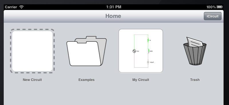
In this screen shot, there are 4 icons: a New Circuit icon that can be tapped to create a new circuit, an Examples folder, a circuit called My Circuit, and a special folder called Trash. The title of the screen also says “Home”, because this is the Home folder.
To create a new circuit, tap on the New Circuit icon.
To open a circuit, first tap it to select it, then tap it again to edit it.
When you select a circuit by tapping it, you are given the ability to perform some further actions at the bottom of the screen:

From left to right, these actions are:
- Edit brings up the main circuit editor and simulator. This is equivalent to simply tapping the circuit a second time.
- Share you can send the selected file to a variety of places (see Sharing and Printing for details).
- Settings to configure the circuit (see Circuit Settings for more details).
- Clone lets you create an exact duplicate of the selected circuit.
- Trash moves the circuit to the Trash folder.
When no circuits are selected, you will still have access to the Settings action. This will allow you to change the settings of the template circuit that is used whenever you create a new circuit.
Folders
You can place your circuits in folders to keep better organized. iCircuit has 3 folders by default:
- Home is the root folder and is where you’ll usually keep your circuits
- Examples contains some standard circuits that demonstrate some of the available elements in the app.
- Trash contains circuits that you no longer want, but have not yet completely deleted. (Better safe than sorry!)
- Inbox is where files opened from the web or from other programs are put. It is not visible unless there are files in it.
You can move a circuit from one folder to another by editing its Settings. In the Settings dialog, you can tap the Folder property and choose which folder it belongs in:
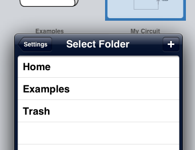
You can also press the + button to create a new folder to put the circuit into.
You cannot explicitly delete folders, instead empty folders are automatically removed from the display.
Examples Folder
The Examples folder is special. If you move a circuit out of the Examples folder and into any other (such as the Trash), then the file will be recreated in its original condition. The example file will also be recreated if you rename it.
This means that you are free to play with example files without ever having to worry about losing their original versions.
If you ever want the original back, simply rename the modified version to something else or move it to a different folder. You will see that the original example file will re-appear under its original name and with its original contents.
Trash Folder
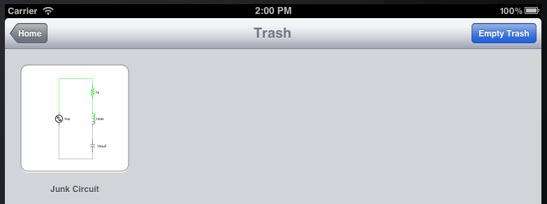
The Trash folder is also special. Only files in this folder can be permanently deleted.
When you navigate to this folder, there will be a new action exposed called Empty Trash. Pressing that button will give you the ability to permanently delete all the circuit files in the trash.
Share and Print
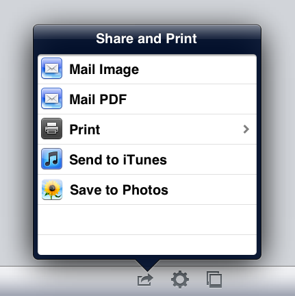
The following actions are available to share your circuit files:
| Action | Outcome |
|---|---|
| Mail Image | Opens the Mail app with a PNG image of your circuit, the circuit file, and a parts list attached to the message. |
| Mail PDF | Opens the Mail app with an scalable PDF image of your circuit, the circuit file, and a parts list attached to the message. PDFs are best if you plan on printing the circuit. |
| Prints the circuit to a network connected printer. | |
| Save to iTunes |
Saves the circuit to the CIR file format that can be opened by other versions of iCircuit. For example, the Mac OSX version can open these files. You can retrieve this file by going to iTunes, selecting your device, choosing the Apps section, scrolling down to File Sharing, then selecting iCircuit: 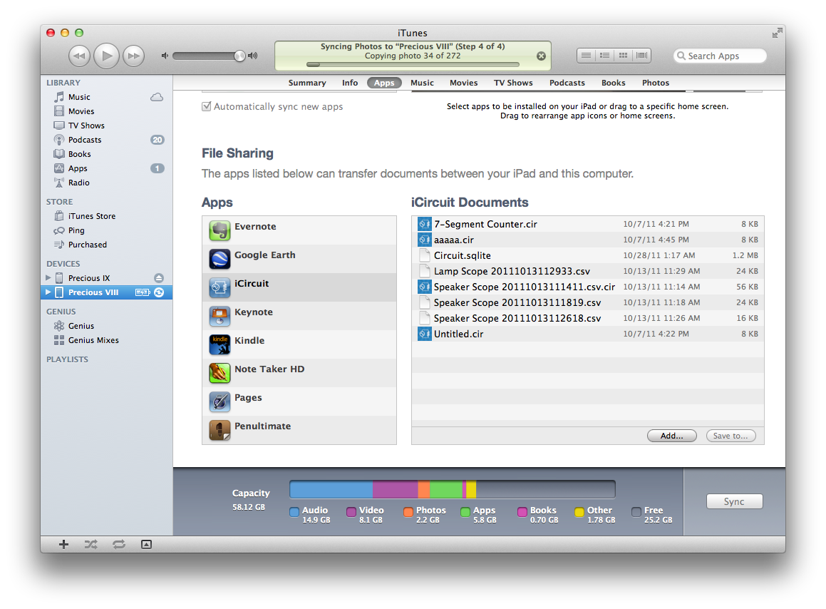
You can then drag files out of the Documents list onto your machine. WARNING Leave the file Circuit.sqlite alone. It is the main database used by iCircuit and tampering with it could result in you losing all of your circuits. |
| Save to Photos | Saves the circuit as a PNG image to the Pictures app on the device. |
Circuit Settings
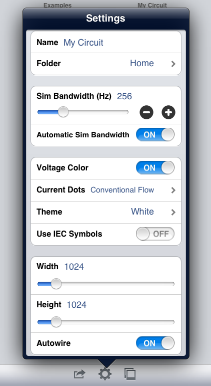
There are a variety of settings that you can configure on a per-circuit basis. These are:
- File Settings
- Name is the name of the circuit file.
- Folder is folder that contains the circuit file.
- Simulator Settings
- Sim Bandwidth (Hz) is the frequency that the fixed time step integrator uses when solving the circuit equations. In general, you will want to make sure that this value is at least 8X the highest frequency that you care to measure in the circuit.
- Automatic Sim Bandwidth is a convenience you can use to make sure that the Sim Bandwidth is always high enough. It is recommended that it always remain ON so you don’t have to worry about getting the Sim Bandwidth right.
- Visualization Settings
- Voltage Color enables the coloring of different nodes of elements depending on the voltage at those nodes. These colors are relative to the ground of the circuit. Voltages above ground will be shaded green while voltages below ground will be shaded red.
- Current Dots enables an animation of the current through the circuit branches. Current is represented as little yellow dots whose speed and direction depend on the magnitude and direction of current through a branch. You can choose to visualize current using Conventional Flow, Electron Flow, or you can disable this animation.
- Theme allows you to choose the overall coloring of the circuit. Three themes are include: white (the default), black which uses a black background, and paper which simulates a pencil drawing on engineer’s paper.
- Use IEC Symbols is used to enable the IEC shapes for elements when those shapes differ from their American counterparts.
- Editing Settings
- Width and Height control the maximum dimensions of the circuit. There are 128 units per inch. The default circuit size of 1024x1024 is therefore 8”x8”.
- Autowire enables the automatic rerouting of wires when you move elements.
Editing
The majority of the editing area is comprised of an animated and interactive display of the circuit. This animation displays the current flow through paths and voltages at nodes.
There is also a main toolbar with the following actions:
- Circuits takes you back to the Circuit Browser.
- Undo gives you access to the revision history of the circuit. (See Undo and Redo)
- Add Elements displays and hides the library of elements that can be added to the circuit. (See Adding Elements)
- Wiring enables and disables the wiring mode. (See Wiring Mode)
- Scope toggles the visibility of the Scope. (See Scope)
- Info used to display the selected element parameter editor. (See Element Parameters)
- Tools gives you access to the Circuit Settings and Share and Print dialogs that are also available in the Circuit Browser.
- Pause allows you to temporarily pause, and subsequently reset, the simulator.
Selecting Elements
To select an element tap on it once in the editor. To deselect it, tap once in a blank part of the circuit.
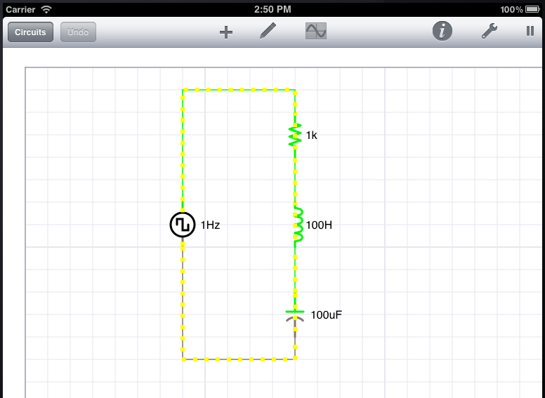
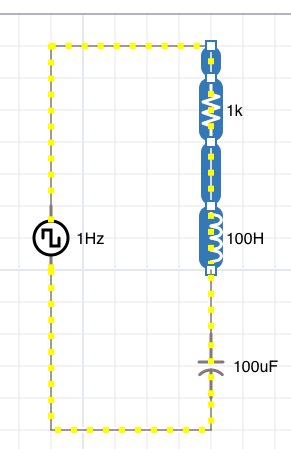
You can also select multiple elements using the lasso tool. To activate the lasso, press and hold your finger in a blank part of the circuit, wait one second, and then move your finger. You will begin drawing a selection region. All elements completely inside that region will then be selected.
Press, wait, then drag:
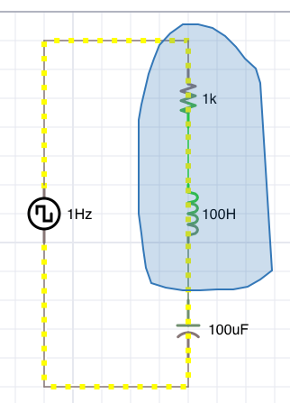
Release:
You can extend the selection by tapping on an already-selected element. This will reveal the Edit Menu with the option “Select”:
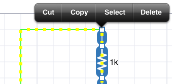
Pressing Select will have different affects depending on what’s already selected, but it will always select more elements:
- If you already have some elements in a column selected, the Select will select the entire column.
- If you have some elements in a detached part of the circuit selected, it will select all the elements in that detached part.
- Otherwise, it will select all of the circuit.
To reliably select all the elements in a circuit, tap in a blank area while nothing else is selected to reveal the Select All menu. Tap that and everything will be selected. This is convenient for moving the whole circuit.
Moving Elements
To move elements:
- Select the elements you want to move,
- Press and hold your finger down on top of one of the selected elements,
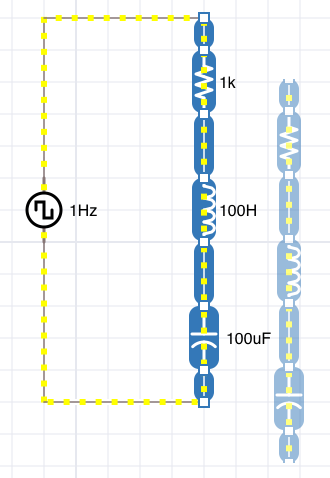
- Move your finger and you will see a ghost of those elements move with you.
- When you are satisfied with the new position, release your finger.
When moved, elements will snap to the grid and their attached wires will autoroute to stay connected.
Because elements can be singly-selected when you press down on them, you can combine the selection and move operations into one press, wait, then move gesture.
If you attempt to move elements over other elements, then the move operation will be aborted.
There is one exception to this rule: if you move a simple two-node element (such as a resistor) over a wire, and that wire perfectly lines up with that element’s nodes, then the element is allowed to move and will be connected to the wire just as you would expect.
Deleting Elements
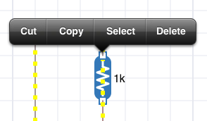
Elements can be deleted using the Edit Menu. To invoke the Edit Menu:
- Select one or more elements,
- Tap and release once on any of the selected elements.
Press the Delete item to delete all the selected elements.
Clipboard
Elements can also be added to and pulled from the clipboard using the Edit Menu. To invoke the Edit Menu:
- Select one or more elements,
- Tap and release once on any of the selected elements.
With this menu, you can either cut or copy the selected elements to the clipboard.
To paste elements on the clipboard, tap once in an empty part of the circuit while no other elements are selected. This will reveal a new menu with the option to paste. Tapping Paste will place whatever is on the clipboard as close to your tap position as possible (care is taken to make sure these elements do not overlap any existing elements).


Adding Elements
Pressing the + button on the toolbar will toggle the visibility of the elements library.
The library is a scrollable list of elements that can be added to the circuit. You can scroll the list by flicking left and right.
To add elements from the library to the circuit, you drag them in the same way that you move elements. That is, you press, wait a second, then drag them onto the circuit.
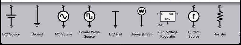
For a full list of elements that can be added, see the Element Reference section of this manual.
Element Parameters
All elements have some parameters that can be configured. For example, resistors can have their resistance set, transistors can have their current gain set, and ADCs can have their number of bits set.
To edit these parameters:
- Select the single element whose parameters you want to change,
- Press the Info button on the toolbar,
- or double-tap the element.
The Editor will appear when you complete steps 2 or 3.
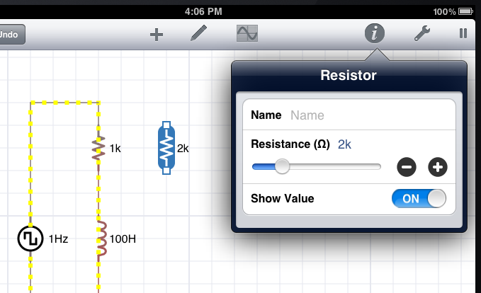
With a resistor selected, there are three parameters that can be edited:
- Name Almost all elements can have a name assigned to them
- Resistance The resistance of the resistor specified in Ohms. (In this case, it’s 2 kOhm.)
- Show Value Whether to show the resistance in the circuit diagram
To modify numerical values, you can either use the keyboard or a combination of the slider and magnitude buttons.
- Keyboard The keyboard can be invoked by tapping on the blue number. You can type any number followed by an SI magnitude prefix. For example, 2m is short for 0.002 and 2M is short for 2,000,000. While the keyboard is displayed, you can also copy and paste values using iOS’ clipboard using the normal text-editing gestures.
- Slider The slider lets you vary the value interactively. While it’s difficult to enter an exact value (you should use the keyboard for this), it is useful for watching how the circuit reacts to changes in the value.
- Magnitude Buttons The + and - buttons change the value by increasing and decreasing its power of 10. This is useful for quickly seeing the affect of large changes in the value.
For a full listing of which parameters can be configured on which elements, see the Edit Parameters section of each element in the Element Reference.
Undo and Redo
iCircuit is continuously saving your work and maintains a history buffer of 200 edits throughout the lifetime of your circuit file.
You can undo items in that history by tapping the Undo button in the toolbar.
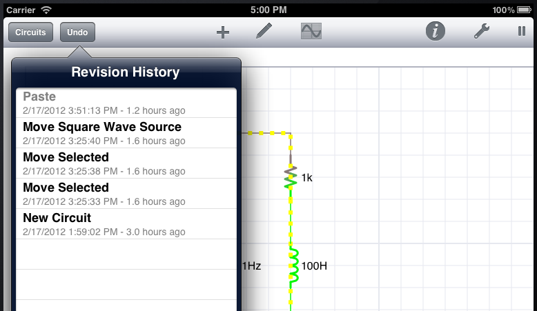
To redo previously undone actions, press and hold the Undo button. This will reveal the Revision History list. Actions that have been undone appear in gray in this list. while actions that are still in affect are shown in black. Tapping an item of that list will rewind or fast forward history to make the selected action be the most recent action.
If you make an edit while some actions are undone, then those actions will be lost forward.
Meter
The Meter acts as a virtual multimeter and samples the various properties of elements at a frequency of about 2 Hz.
Just as every element has a list of parameters that can be edited, each element has a list of properties that can be sampled by the meter. The list of properties that can be metered for each element can be seen in the Meter Information section in the Element Reference.
You can hide the Meter by pressing the X in the upper-right corner, but it will always come back when a single element is selected.
Multimeters are great for understanding some general properties of elements, but if you have an AC circuit, where voltages and currents are changing faster than 2 Hz, then you will need to monitor those properties using the Scope instead.
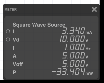
To add properties to the scope, simply tap their name in the meter. The signal will then be illuminated with the same color as it appears on the scope. To remove the property from the scope, tap its name again.
Not all of the properties that can be viewed on the Meter can be viewed on the Scope. Those that can are designated with a little circle icon next to their name. In the Square Wave Source shown above, only the I and V properties can be viewed on the Scope. The Element Reference shows which properties can be scoped by designating them with the parenthetical “(scope)”.
Reversing the Polarity Measurement
Some elements allow you to “swap” the way measurements are taken of their values. This simulates swapping the positive and negative leads of the measuring instrument.
This is useful if iCircuit is showing values as negative when you think that they should be measured as positive. This commonly occurs when measuring current. Since iCircuit doesn’t know which direction of current you consider to be positive, it must guess and will only be right 50% of the time.
Scope
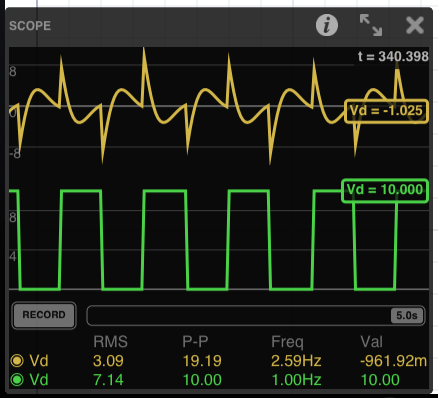
The Scope is used to monitor element properties over time. When they’re added to the scope they are referred to as “channels”. The Scope is a plot where the horizontal axis is time and the vertical axis is in the units of whatever property is being monitored. The Scope displays a fixed amount of time and automatically scrolls to keep “now” on the right edge of the plot.
In addition to that plot, the scope also measures time varying statistics of the channel such as its RMS value and its peak-to-peak value. These value are displayed at the bottom of the scope.
You add channels to the scope by selecting properties in the Meter. When a property is being monitored on the scope, it is illuminated on the Meter. See the the documentation for the Meter for details.
To change the amount of time viewed by the scope, you use two fingers in a spreading and pinching gesture that will expand and contract the amount of time shown.
Scrolling Back in Time
The Scope’s recording can be temporarily paused so that you can focus on a moment in time. To pause the scope, toggle the RECORD button.
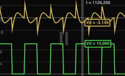
When you do so, the value cursor will appear, and a little pause icon will be drawn in the middle of the plot to remind you. The cursor can be moved to read instantaneous values at different moments in time by dragging your finger over the plot’s surface.
You can also rewind to time not shown on the plot by dragging the little time indicator nub in the bar to the right of the RECORD button. The nub shows you how much and where in history you are viewing in the plot. If the nub is all the way to the right, then you are viewing the most recent data. If it is all the way to the left, you are viewing its oldest data.
Scope Settings
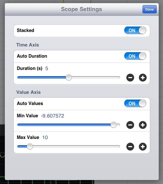
Not all Scope settings can be configured using its display surface. For advanced options, you will need to invoke the Scope Settings dialog by tapping the Info button on the Scope display. This will reveal the dialog shown in the picture above. In this dialog, you can change the following settings:
- Stacked is whether to display multiple channels on their own individual plots or whether to put them all on one plot. Stacked set to ON is best for signals that use different units. Stacked set to OFF is best when comparing two similar signals.
- Time Axis
- Auto Duration monitors the channels on the scope and sets the amount of visible time necessary to capture about five periods of the waveform being displayed. This works well for normal AC signals, but can be useless if your signals’ frequency varies with time. If you have time varying frequencies, it’s best to disable Auto Duration and set the Duration to an appropriate value.
- Duration is the amount of time visible on the plot.
- Value Axis
- Auto Values Just like Auto Duration, Auto Values monitors the displayed channels and attempts to change the value axis minimum and maximum displayed values to fit the entire wave form. This is usually what you want, but there are times when such automatic zooming can be confusing. In those cases, it’s best to turn Auto Values off and force the min and max displayed values.
- Min Value is the minimum value displayed on the plot. This is the value of the “bottom” of the plot.
- Max Value is the maximum value displayed on the plot. This is the value at the “top of the plot.”
Triggers
The scope can be configured to perform continuous triggering on rising edges or falling edges of a signal. This is very useful for analyzing high-frequency data or for data whose frequency changes over time.
To enable triggering, you must first pause the scope (tap the RECORD button). You can now single-tap on the cursor value for the track you want to trigger on.
There are three trigger modes: Off, Rising-edge, and Falling-edge. When not Off, there will be a little icon next to the cursor value. Tapping the cursor value will toggle through the 3 modes.
When not off, a trigger’s value can be changed by dragging the cursor up and down.
When there is an active trigger, the RECORD button will change to be a TRIGGER button. When you press the TRIGGER button (un-pause the scope), the display will only update on trigger events.
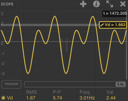
In this example, a rising-edge trigger has been configured for 1.663 V. The the TRIGGER button is pressed, the scope display will only update when one of the larger positive peaks is encountered.
Custom Expression Tracks
The scope can display more than just element values, it can display arbitrary mathematical expressions (that may or may not involve element values). This is useful for measuring differences between signals, or generating comparison signals.
To add one of these mathematical tracks, tap the + icon on the iPad, or select More, Add Track on the iPhone. A dialog will be presented where you can type your desired expression.
For instance, let us measure the effect that a capacitor has on the following circuit.
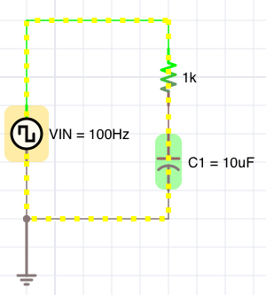
We wish to measure the difference in voltages between the voltage source and the voltage drop across the capacitor. To do that, we add a track to the scope using the following expression:
VIN.Vd - C1.Vd
If we also plot VIN.Vd and C1.Vd, our scope would look like this:
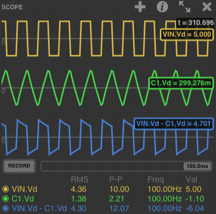
You can add any expression you want to the scope using any of the rules specified in the Expressions section of this manual.
Dependent Sources
Dependent sources are sources that use mathematical expressions to generate their values. These expressions, most commonly, involve values from other elements in the circuit but can also just be purely generative.
Both the Voltage Source and Current Source can be configured to be dependent. This is done by setting their Waveform parameter to Dependent. When this is done, you can enter any expression into the v(t) or i(t) parameters.
Please see the Expression Reference for details on what can be specified.
Example: Referencing a Resistor

Let’s imagine that you name the resistor R1. You can then
reference the current through it as R1.I. The dot notation
can be used to pick any of the scope-able variables in the Meter (any value that has a circle by its name).
R1.I, therefore, references the current through the
resistor, the same current seen in the meter.
In this circuit we have created a current source that outputs the same amount of current as what is consumed by R1. This means that it will generate the same voltage as what is driving R1. You can see that it has induced a +5 V above the unnamed resistor.
iCircuit does not know what direction of current should be deemed positive or negative. For that reason, the Meter allows you to toggle the polarity of measurements. If we toggle that polarity in R1, then that will influence the current produced by the dependent current source. The result of toggling that measurement direction is shown in the picture below. You can see that it has resulted in a -5 V potential.

It is therefore very important that you verify positive and negative values of currents in the Meter before referencing them using dependent sources.
Example: Generating an AM Signal
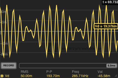
Dependent sources don’t have to rely on other elements’ values, they can rely on time too. This means that it is easy to generate very complex signals. Let us consider the problem of carrying a 200 Hz signal on a 1700 kHz carrier wave. We can accomplish this using the following expression:
0.1*cos(200*2*pi*t)*cos(1700k*2*pi*t)
This expression multiplies a 200 Hz sine wave with an amplitude of 0.1 by a 1700 kHz sine wave with amplitude 1. Here is a picture of it in operation:
Example: Generating an FM Signal
To make the possibilities further concrete, let’s look at generating an FM carrier for our 200 Hz signal. In FM, the signal produces changes in the frequencies of the carrier about a base frequency. As an expression, it can be specified as:
cos(90.3M*2*pi*t + 75k/200*cos(200*2*pi*t))
In this expression, we are using a carrier with a base frequency of 90.3 MHz, we deviate from the base frequency by 75 kHz (the channel bandwidth) and it’s carrying our 200 Hz signal. As you can see, dependent sources allow for some fun experiments!
Note on Simulator Bandwidth
The automatic simulator bandwidth calculator for iCircuit is not able to understand dependent sources. Because of this, it will most likely choose a bandwidth much lower than what is really needed. For example, in the FM signal example, the simulation bandwidth had to be manually set to 800 MHz in order to produce good simulation results.
Subcircuits (Custom Elements)
Subcircuits provide a way to modularize your circuit designs and as a means for creating custom elements. Combined with Dependent Sources, subcircuits are a very powerful tool.
Any circuit can be turned into a subcircuit. This is done by adding Port elements to the circuit. Below is an image of a subcircuit that will has three ports.
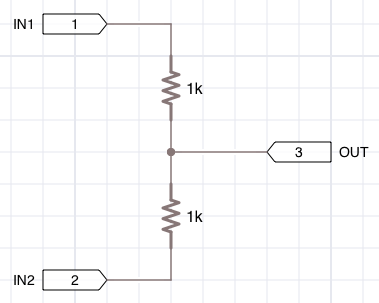
Each port has a name (optional) and a pin number. Here, we have pins 1 and 2 assigned to IN1 and IN2. The third port is a combination of the two signals.
Ports are bidirectional (they a resistance-less connections) but, in this case, they are laid out in a way that implies that pins 1 and 2 are inputs while pin 3 is an output. iCircuit, however, does not distinguish between input and output ports.
To consume a subcircuit, the Subcircuit element is used. This element has a parameter called Subcircuit File. Assuming that we named the previous circuit “Combine”, we can create a consumption circuit:
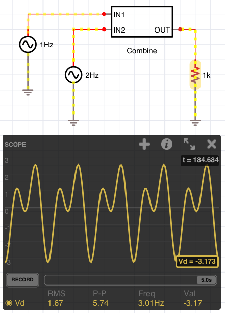
You can see the the subcircuit takes on the appearance of an IC. The pin numbers assigned to the ports are used to layout the chip in standard DIP order.
Important Notes
- Ports are bidirectional and offer 0 resistance.
- It is easy to accidentally create short circuits by connecting ports in the subcircuit directly to a voltage source (including ground). If such a port is connected to a voltage source in the consuming circuit, then matrix errors may occur. As a rule of thumb, never connect a port in the subcircuit to a voltage source or ground.
- When using dependent sources in a subcircuit, the source can only reference elements in that subcircuit.
Expressions
Expressions can be used to specify element parameters and as the values of dependent sources.
You are also able to enter arithmetic expressions that will get evaluated after you press return. For instance, all of the following will produce the given value:
| Expression | Value |
|---|---|
| 2+2 | 4 |
| 1+1/8 | 1.125 |
| (1+1/8)*1k | 1125 |
| sin(pi/6) | 0.5 |
Referencing other Elements
An expression can reference values from other elements in the circuit. This is done by naming the element you want to reference and then using the following syntax in the expression:
ElementName.ValueName
where ElementName is the name you assigned to the element and ValueName is the name of one of the scope-able values seen in the Meter. Scope-able values are those with circles by their names.
For instance, if there was an element named R1, you could reference its current using the expression R1.I. The resulting value will be exactly the value as shown in the multimeter at the time the expression is evaluated. Please note that the Reverse Polarity option in the meter will affect this value.
You can, of course, mix element references with other mathematics. For instance, the following is a completely valid way to generate the 10 times the absolute value of the voltage across R1:
10 * abs(R1.Vd)
Functions
You are able to use the following math functions in these expressions:
| Function | Interpretation |
|---|---|
| abs(x) | Absolute value of x. |
| acos(x) | An angle, θ, whose cosine is the specified number measured in radians, such that 0 ≤ θ ≤ π. |
| asin(x) | An angle, θ, whose sine is the specified number measured in radians, such that -π/2 ≤ θ ≤ π/2. |
| atan2(y, x) | An angle, θ, measured in radians, such that -π ≤ θ ≤ π, and tan(θ) = y / x, where (x, y) is a point in the Cartesian plane. |
| cos(x) | Cosine of x. |
| cosh(x) | Hyperbolic cosine of x. |
| exp(x) | ex. |
| log(x) | The natural (base e) logarithm of x. |
| log(x, b) | The logarithm of x with base b. |
| max(x1, …, xn) | The larger of all the arguments. |
| min(x1, …, xn) | The smaller of all the arguments. |
| pow(x, y) | The number x raised to the power of y. |
| sign(x) | A number that indicates the sign of x, as shown in the following table. -1 if the x is less than zero; 0, if x is equal to 0; +1 if x is greater than 0. |
| sin(x) | Sine of x. |
| sinh(x) | Hyperbolic sine of x. |
| sqrt(x) | Square root of x. |
| tan(x) | Tangent of x. |
| tanh(x) | Hyperbolic tangent of x. |
Global Variables
The following global variables are available:
| Variable | Interpretation |
|---|---|
| t | The current simulation time in seconds. |
Constants
The following constants are available:
| Constant | Interpretation |
|---|---|
| e | Euler’s Number, the base of the natural logarithm. |
| pi | Ratio of a circle’s circumference to its diameter. |
Element Reference
Please see the Element Reference page for a detailed list of all elements.